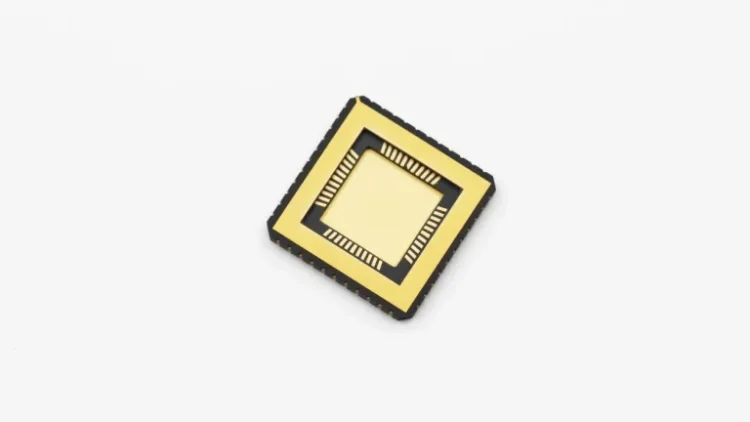
Ceramic igniters are widely used in gas appliances, pellet stoves, boilers, grills, and industrial combustion equipment. Their basic function is straightforward: electrical energy is converted into heat, allowing the ceramic heating element to reach a temperature high enough to ignite gas or solid fuel.
Unlike spark ignition systems or continuously burning pilot lights, ceramic igniters use a hot-surface ignition principle. When power is applied, the internal resistance element rapidly heats the ceramic body, producing a high-temperature surface that comes into direct contact with the fuel or fuel-air mixture.
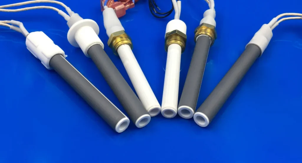
01 What Is a Ceramic Igniter?
A ceramic igniter is an electrical heating component manufactured from high-temperature ceramic materials, with silicon nitride (Si₃N₄) and silicon carbide (SiC) being two commonly used material systems.
The basic structure consists of a ceramic rod or plate with an integrated resistive heating element. Once an electrical current passes through the heating circuit, resistance generates heat. The ceramic body transfers the generated heat toward the ignition surface, creating the high-temperature zone required for fuel ignition.
Compared with conventional spark electrodes and pilot lights, this approach provides a direct and repeatable method of initiating combustion.
02 How Does a Ceramic Igniter Work?
The ignition process can be divided into several stages.
Step 1: Electrical Power Is Applied
When the appliance requires ignition, its control system supplies power to the ceramic igniter. Current passes through the embedded resistive heating element.
Step 2: The Igniter Rapidly Heats Up
The heating element converts electrical energy into heat. Depending on the design, power rating, and operating conditions, the ignition surface can reach temperatures of approximately 1,000–1,350°C.
Step 3: Fuel Reaches the Hot Surface
For gas systems, the fuel-air mixture passes near the heated surface. In pellet and biomass systems, the igniter is positioned close to the fuel. Once the required ignition temperature is reached, combustion begins.
Step 4: Combustion Becomes Self-Sustaining
After the fuel has ignited, the control system may switch the igniter off or maintain heating for a defined period, depending on the equipment design and ignition strategy.
03 Typical Performance Parameters
The actual specifications vary according to the application and igniter design. Typical parameters may include:
| Property | Typical Range | Notes |
|---|---|---|
| Ignition Surface Temperature | 1,000–1,350°C | Depends on material and design |
| Heat-Up Time | 10–60 seconds | Related to power and structure |
| Electrical Power | 50–400 W | Application dependent |
| Operating Voltage | 120 / 240 V AC | Common system voltages |
| Ceramic Material | Si₃N₄ / SiC | Selected according to operating conditions |
| Thermal Shock Resistance | Excellent | Important for repeated heating cycles |
| Typical Service Life | 3–7 years | Varies with operating conditions |
These values should be treated as general reference ranges rather than universal specifications. The required voltage, power, dimensions, and heating temperature need to be matched to the equipment.
04 Why Are Ceramics Used for Hot-Surface Ignition?
The ceramic material is not simply a structural housing. Its thermal and electrical properties directly determine how the igniter performs.
High-Temperature Stability
Ceramic materials can maintain their structural integrity at temperatures where many conventional materials would soften, oxidize, or deteriorate. This allows the ignition surface to reach the high temperatures required for reliable fuel ignition.
Thermal Shock Resistance
Igniters are frequently exposed to rapid heating and cooling. Silicon nitride and silicon carbide can withstand these repeated temperature changes, reducing the risk of cracking caused by thermal stress.
Electrical Insulation
The ceramic body electrically isolates the heating circuit while allowing heat to transfer toward the ignition surface. This combination of electrical insulation and thermal performance is particularly useful in compact ignition assemblies.
Chemical and Oxidation Resistance
During combustion, the igniter may be exposed to hot gases, fuel residues, and combustion byproducts. Advanced ceramic materials offer good resistance to oxidation and chemical attack, helping maintain performance over repeated operating cycles.
05 Where Are Ceramic Igniters Used?
Hot-surface ceramic ignition is used across a wide range of heating and combustion equipment.
Residential and Commercial Heating
- Gas furnaces
- Boilers
- Water heaters
- Heating appliances
Pellet and Biomass Equipment
- Pellet stoves
- Pellet boilers
- Biomass burners
- Wood-pellet heating systems
Cooking Equipment
- Gas grills
- Commercial ovens
- Fryers
- Other gas-fired cooking equipment
Industrial Equipment
- Industrial burners
- Process heating systems
- High-temperature combustion equipment
The required igniter design can vary considerably between these applications because fuel type, ignition position, heating temperature, power supply, and operating cycle are different.
06 Ceramic Igniters Compared with Conventional Ignition Methods
Ceramic hot-surface ignition offers several practical advantages over traditional ignition approaches.
Compared with standing pilot lights, ceramic igniters only consume electrical power during the ignition cycle rather than continuously maintaining a flame.
Compared with spark ignition, hot-surface ignition does not depend on maintaining a spark gap or electrode alignment. This can be useful in applications where ignition reliability is affected by moisture, contamination, or mechanical positioning.
The result is a compact ignition system with relatively simple electrical control and no moving ignition components.
07 Key Design Considerations
Selecting a ceramic igniter requires more than choosing a suitable temperature rating. Several operating parameters should be considered together.
Power Supply
Insufficient voltage or power can prevent the igniter from reaching the required ignition temperature within the specified time.
Installation Position
The hot surface must be positioned correctly relative to the fuel flow. Poor positioning can result in delayed ignition or uneven heating.
Thermal Environment
After ignition, the ceramic element may continue to receive heat from the flame. The igniter must therefore be able to withstand both its own heating cycle and the surrounding thermal conditions.
Operating Cycle
Frequent start-stop operation places additional thermal stress on the ceramic and heating circuit. The control strategy should therefore match the igniter’s rated operating cycle.
08 Common Problems and What to Check
A few basic checks can help identify common ignition problems.
Slow heating: Check the actual supply voltage and power. Insufficient electrical input can significantly increase heat-up time.
Failure to ignite: Inspect the ceramic body for cracks or damage and check the electrical resistance of the heating circuit.
Short service life: Excessive cycling, continuous operation, incorrect installation, or unsuitable power conditions can accelerate degradation.
In practice, the igniter should always be evaluated together with the control circuit, mounting structure, fuel system, and operating environment.
09 Development Trends in Ceramic Ignition Technology
Current development is mainly focused on faster heating, improved durability, and better energy efficiency.
New ceramic materials and heating circuit designs are being developed to shorten heat-up times while maintaining high-temperature stability. Higher-performance ceramic systems may also support more demanding fuel types and operating environments.
At the same time, electronic control systems are becoming more sophisticated. More accurate power control can help reduce unnecessary energy consumption and avoid excessive thermal loading on the igniter.
Conclusion
Ceramic igniters use a relatively simple hot-surface ignition principle, but their performance depends on the interaction between ceramic material, heating circuit, power supply, installation structure, and operating conditions.
Silicon nitride and silicon carbide are particularly suitable for this type of application because they combine high-temperature stability, thermal shock resistance, electrical insulation, and good resistance to demanding combustion environments.
For appliance manufacturers and industrial equipment designers, the right ceramic igniter should therefore be selected according to the required ignition temperature, heating time, power, dimensions, fuel type, and operating cycle rather than by temperature rating alone.
INNOVA Supplies provides customized ceramic igniters for pellet stoves, biomass combustion systems, gas appliances, and industrial high-temperature ignition equipment. Different ceramic materials, dimensions, power ratings, electrode configurations, and mounting structures can be developed according to application requirements.